Radionics Posts

Radionics Schematic: Super Simple Three Dial


Presented here for your delectation is a super simple three dial radionics schematic. There is no techno jargon, or standard schematic imagery. The circuit is simple as shown. The black lines represent wires, and their connections. The bottom row of wiring simply shows that the last post on each potentiometer is connected to the last post on the next.

This type of circuit is also known within radionics as a passive resistance circuit. There are no coils, crystals, or amplifiers within this circuit, but that does not detract from its raw power. Generally, this circuit can be used to copy homeopathic remedies, or for imbuing a witnesses sample with a particular trend. For the latter, the witness sample would be placed on the output, and the trend would be placed on the input. The trend could take the form of a remedy, written or pictorial intention, etc. For use in agricultural radionics for instance; fertilizer, or pesticides could be placed on the input plate, and their rates dowsed for with a pendulum.

What you will need:


  • Two copper discs, or copper sheets. Copper is not necessary, but it by far the best candidate for our purpose. If you are struggling to find copper, you can use brass, aluminium, or stainless steel as a last resort. If you are extremely lucky, you can even use gold, or silver sheet!


  • Three potentiometers. These are “10K linear potentiometers” run an internet search, or look on places like ebay for these components. Failing that try your local electronics supplier such as Maplins, or Radio Shack.


  • You will need a length of wire to wire up the potentiometer. Some researchers use solid clear enameled copper wire, but I find regular bell wire or equipment wire works just as well. Again, you can get some regular stranded single core wire from hardware stores or online. You will probably need less than a meter for this, but just to be on the safe side, and to have some surplus for a future project, get hold of a meter, or several feet worth.


  • You will also need something for stripping the wire; a pair of wire cutters can be used once you get the hang of it, or a craft knife.
  • In order to connect the wires to the potentiometers, you will need to Solder. For a beginner with no electronics experience, this is often a stumbling block. You can get hold of cheap soldering irons on the internet. You will only need something rated at 25-30W. Get yourself a book on soldering for beginners, and a reel of silver based solder. It really is quite easy to do, and once you learn this new skill you can use it for future projects.If this still puts you off, there is a product called “Wire glue” which will literally allow you to glue the wires to the potentiometers and plates. Failing that you could use some electrical tape. I wouldn’t advocate this, but it is possible as a last resort.


  • You will also need some type of box to mount everything in. Charles Cossimano suggests a shoe box. This can work well if you are on a budget. Personally, I use wooden boxes where possible. However, if you really have to, an ABS plastic box will work o.k.


  • In order to mount the potentiometers. You will require a drill, and selection of drill bits.
  • Finally; x4 bolts x8 washers, and at least four nuts. To top this off three potentiometer dials. Again, these are available from places such as Ebay, and Radio Shack, etc.


Once you have all your components you can begin to build to the above diagram. You should have chosen an enclosure/box which will allow you enough room to mount everything on one surface, usually the top. If it doesn’t, not to worry; some people will mount the plates on the top surface, and the dials on one of the sides to make more room.


It’s quite simple from here on in. Use your intuition, and build an instrument which you find visually and aesthetically appealing, as this will increase its potential. You are imbuing the device with your own power, use it wisely.


This information is free to copy and distribute. All I ask as my copyright condition is that you attribute the work back to BerkanaPath.com. These posts and diagrams take a great amount of work, and it is saddening when people abuse the work of others. This is why I am being forced to watermark all of my intellectual properties. Thank you for understanding.


Copen Restoration Project 1

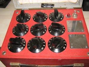
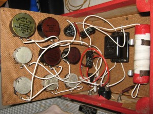
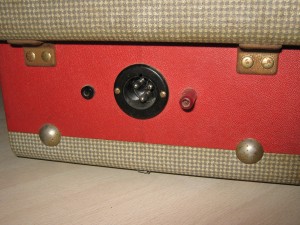
I have been fortunate to acquire three original Bruce Copen Radionic Instruments. Unfortunately, they were in quite a state when I received them. The images below are of a nine dial base 10 resistance instrument. I can’t seem to find any information on this, but judging by the pass dates on the old Colvern potentiometers, it is from the early to mid 50s. Looking at the general grime build up and rust on the nickel fittings, I can only assume it had been stored in damp conditions for a number of years, most likely in a shed or barn. It is sad to think that these impressionable instruments were left neglected, their original owner no longer able to care for them. At one point, they were used extensively to manufacture homeopathic remedies. A lot of the surviving vials came with the lot. However, I have no use for vintage remedies so have stored them away. If anyone is interested in the vials, please get in touch.


I am slowly, working my way through the restoration, and am making good progress. I have decided to tackle this nine dial instrument first, as it is the easiest. Currently, I have fully cleaned up the casing, and replaced the fixings with brand new nickel latches and hinges from the original company. I have also replaced the leather strap handle on the front. The inside lid has been lined with red card, reflecting the original intentions of using paper, which was too damp and dirty to re-use. I will upload some new photos on another post over the next few weeks. Currently, I’m working on the control panel. Sadly only one of the original potentiometers is in full working order, luckily it is the one which can’t be easily replaced. Copen’s wiring is the most unusual. On this nine dial instrument, you have three logarithmic carbon track 1Megaohm pots, then one 50k linear carbon track. The remaining five in the sequence are Colvern wirewound’s which go from 100k, 10k, 1k, 100R, and 10R I can see the logic in the last five as the resistance steps down, but it’s almost as if Copen has rummaged in his parts box to make up the first four in the stage. This initial 3-4M of resistance is seen in the other instruments I have. It would make more sense if they stepped down like the others and were all linear. It’s a mystery!


The neon lamp on this instrument is wired in an unusual manner, so that it is turned off when the power is in the off position. I suspect the original owner fiddled with the wiring at some point in its history. I intend to rewire the circuit with the same type of wire Copen used, and replace the shot pots, but leave the unusual configuration intact, aside from the neon lamp which I will change to reflect the correct way of operation as seen in the other instruments I have. I look forward to presenting the fully restored instrument to you in a new article.


Update: 18th April

Some of the potentiometers aren’t as damaged as I originally thought. A great deal of tuner cleaner, and they appear to work o.k. Its not to my usual high standards, but what can you expect from components that are sixty odd years old?! The resistances are all o.k and within the manufacturer’s tolerance range, it’s just the movement  is not as fluid or consistent as I would have liked, and this may present a problem when tuning the instrument. I have several wirewounds en route, so it should not be a problem. I would like to keep the originals where I can.

Furthermore, the card lining the lid has begun to peel away. I may just go and Araldite a sheet of thin felted, or vinyled wood to the lid to get around this problem. In any case, I will stick with the red as it compliments the red leather of the case.


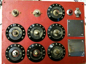
The clogged up dials on the control panel are clearly visible in this image. It has since been completely taken apart and cleaned. The dials look as good as new now.

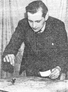
Bruce Copen

Copen dowsing for the stone of destiny

Bruce Copen was a pioneer of radionics. Following on from the works of Abram, Drown and De La Warr. Copen did not start his foray into radionics until the late 1940’s. It was soon after arriving back in England after his service during the second world war that he begun to develop the model Y radionic soil analyser. This was first released to the public in 1947. I have acquired a model Y, which has part dates from the late 50’s so it was in production until at least the 60’s. As for whether it was continued, I am unsure.

In the late 60’s the Mark II radionic computer was released. This marked a string of radionic computers. Each later model being updated by Copen to reflect his ever continuing research, and advancements in the field of radionics, and technology.

Bruce Copen was much more than a radionic instrument manufacturer. He was a Doctor of philosophy and literature, and an avid writer from a young age. During his youth, he wrote a number of stage plays and books of poetry. This was later carried over to written works on the subject of radionics, radiesthesia, and various healing modalities. His contribution to the world of adult education was honoured by him being initiated as Knight of the sovereign order of St. John of Jerusalem.

Mr. Copen was also the founder for the British Radionics Association, and Editor of a number of journals, namely the British Journal of Radiesthesia, Natural Therapeutics, and Seeker. He also founded the International College of Radionics.

Bruce Copen was a renowned dowser. His skills were called upon when the Coronation stone “stone of destiny” went missing from Westminster abbey on Christmas day 1950. His efforts in locating the stone received media attention. Unfortunately, the stone was not located, by any method. A year later it turned up in Scotland. Perhaps Mr. Copen’s endeavours had an unperceived effect upon its reappearance?

In the 60’s, Copen developed the first colour healing instrument. This device was unique in that it held colour rates and transmitted/broadcast them radionicaly rather than using the photon transfer method.

Bruce Copen continued to develop his ideas and models throughout the 20th century. He unfortunately died suddenly at home in 1998.

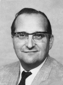
It was his last wishes that his lab be formed into a company. After his death, Harold Rauer became manager of Copen labs ltd. The later models were far removed from anything Copen would have personally developed. These Rauer produced models consisted of the MARS models. A mistake I feel was to digitalise the instruments. Radionics in its most effective form is purely analogue, and Copen’s use of these components in his instruments reflect the nature of radionics.

There is conflicting information as to whether Bruce Copen laboratories is still operating. Some sources have it listed that the company ceased trading in 2010.

Bruce Copen designed and built quality radionic and therapeutic instruments throughout his life. Unfortunately, his skill is now lost to us, but we can remember him for the man and pioneer he was.

Bruce Copen (1923- 1998)

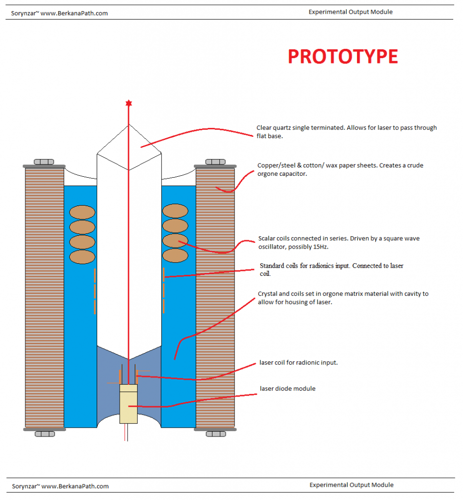
Experimental Output Module

Here is a design I had lying around on my computer. The ultimate goal of the module was to have it cast into a resin block about 2ft tall, with a large clear quartz crystal embedded into it. The laser is used experimentally to allow for light transfer of a radionics signal, it could also be used to pulse audio frequency into the heart of the quartz. The orgone capacitor is used to collapse the gravity field around the regular orgone matrix. While it is a crude version, the orgone capacitor is far more superior to the orgone matrix material. The capacitor needs a lot of work, and it is something which I have begun to look at under the project title of Orgone Stacks. No working version of this experimental module has ever been put together, but it is something I would like to try, if time and resources allowed.

Related Blogs

  • Related Blogs on orgone stacks

Scalar Coil Experiment

I have always had a great deal of success with the toroidal style Scalar coils, such as the like developed by Jon Logan. These fascinating coils emit an energy that has become termed scalar. In popular physics these are linked to zero spin particles such as the Boson. Theoretically, it is possible to create a scalar field by opposing two identical waves which are out of phase with one another. The black projects community term scalar generators as split phase coils. This was something, which eluded both myself, and my physics tutor, who coincidently had done her Phd on Scalar waves. Time has a strange way of combining all the pieces of the puzzle.

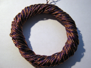
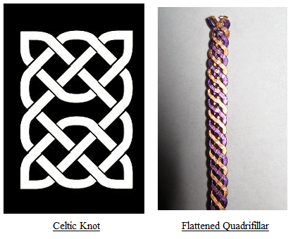
The coils such as the ones developed by Logan, work on the principle that a small scalar field is made when the two identical waves create a magnetic null point at the node where they become out of sync. The genius of using quadrifilar wire allows for a greater degree of nodes to be combined in one small package. One thing which I found uncanny about the quadrifilar wire that Logan uses, is its link to the Chi Knot pattern, A design which was widely used by the Celtic tribes, and Saxons in their artwork.

While impressed with the ability of the regular toroidal scalar coils, I had a niggling idea in the back of my head which I needed to experiment with. It was after reading through several physics papers, and uncovering the Russian research into torsion fields, also termed spin fields, that I came up with an idea based on entropy. I still don’t fully understand how the two are linked to my idea, but I just like to let the imagination run wild. I will briefly highlight the theory behind torsion fields.

Positive Entropy, i.e. (Evaporation of Accetone)= SR (Right Handed Torsion: Time Emission)

Negative Entropy, i.e. (Freezing of Water)= SL (Left Handed Torsion: Time Absorption)

The SR is the repulsive force, and SL is the attractive force, together they create torsion.

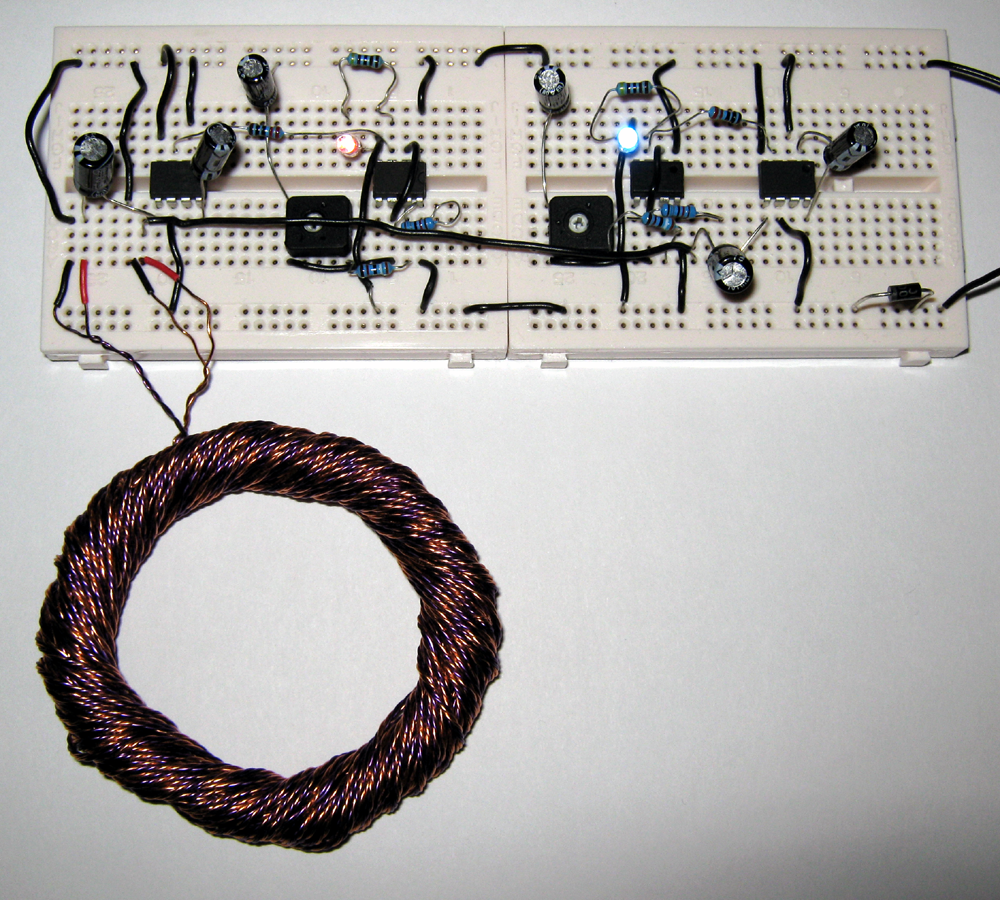
The idea of the two opposing forces led me to use two opposing electron flows in conjunction with the regular toroid setup. To do this, I had to wind the coil slightly different to the way Logan teaches. Instead of using one single strand of wire, I had to use two in parallel. Two 60′ lengths, gets quite difficult to manage, let me tell you!

I persisted, and taped the two lengths together at each end, folded them over, as per Logan’s method and begun to wind them. Once the coil was complete, after some considerable time, I was able to implement the theory.

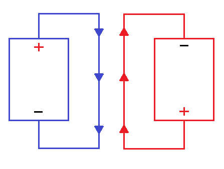
The positive from one oscillator is crossed over with the negative of another. They are as accurate as can be achieved with analogue electronics, but there may be some drift. I managed to get the scopes to read equal 15Hz for each timer, but there is always a small intolerance.

The positive flow and negative flow run parallel to each other within the coil. With positive and negative flows cancelling at the nodes with the applied frequency. It may be that the parallel flow of electrons in opposite directions also has a small scalar effect, giving a performance boost to the coil.

Using a gauss meter on a traditional coil of the same Ohmic value as a base reading. I then set forth and measured the reading of the new coil. The gauss had dropped considerably, leading me to believe that a greater degree of electromotive force had become scalar, rather than magnetic. The experiment seems to have been a success. However, it will require further testing.

Edit:

One thing I would like to alter is the oscillator and amp circuit. The oscillator on its own does not output enough power for the scalar coils. In fact, the majority of the voltage is lost. By adding the power amp, the output is increased considerably. I aim to replace the power amp IC with a power transistor and configure the coil so that the reverse voltage is put back into the circuit rather than lost. This would require some testing, but it is something I have started to work on.

Related Blogs