Radionics Schematic – Simple 3 Dial
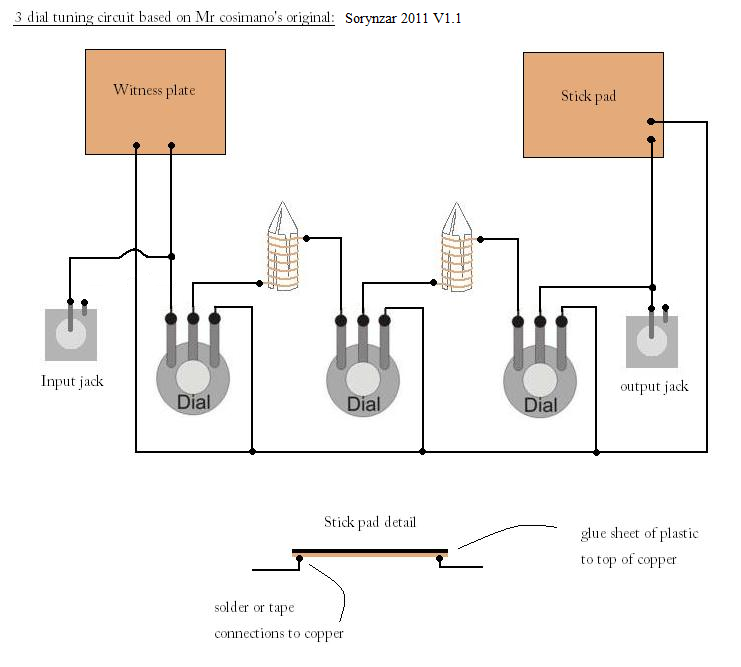
This is a simple radionics schematic, a three dial tuning circuit which you can use today.
The radionics circuit is based on drawings done by Charles Cosimano, aka Uncle Chuckie. It is quite simple to construct. The black lines represent wires, you can use any type of wire you have available. The black dots represent a connection, which ideally should be soldered, but tape could also be used.
You can see the two crystals between the dials, these are wrapped in copper wire and connected to the potentiometers.
The witness plate should ideally be made of copper. The stick pad should also be made from copper with a plastic of your choice covering it. I would go for a plastic which would generate a good static charge, so the type found on coffee cans as mentioned by Uncle Chuckie would be great for this.
The input and output jacks are simple monaural jacks that allow you to add peripheral equipment in the future, being a simple circuit you may want to use it with other devices so the jacks are ideal.
House the radionics circuit inside a box of your choice, I personally prefer to use wood as it can be a good incubator for thought forms and does not prevent orgone from passing freely as some plastics do. You could also use shoe boxes and cigar boxes as Uncle chuckie has mentioned in his books.
If you have any questions on this radionics schematic feel free to comment, and I will do my best to answer.
(2011 update: )
I have made the jacks more electrically stable for this type of circuit. If an electrically powered device were to be connected in the original design it would short across the closed circuit. As it is, the shorter ground pins are left open to prevent the electrons from flowing around the circuit when a suitable device is hooked up. With just the positive pin from the jack connected to the circuit, any RF frequencies emanating from the additional peripherals will flow freely into the circuit/ After all radionics is primarily concerned with radio frequencies, so this will work well. If any electrical devices needed to be connected, I would advise you to connect the short ground pins to an electrical or Earth ground source.
Related Blogs
- Related Blogs on Radionics
- More Radionics… the Global Grids
- QA: What are AcuPoints-Placebo-Radionics-etc
- Related Blogs on radionics circuit
- QA: What are AcuPoints-Placebo-Radionics-etc
- » The art of distant healing with radionics
- COMBINE LAWS OF QUANTUM PHYSICS WITH SCIENCE OF RADIONICS
- Age of Aquarius Healing Clinic « Ragnar111’s Weblog
- Age of Aquarius Energy Techniques The Age of Aquarius has given us …
- Related Blogs on radionics schematic


Leave a Comment