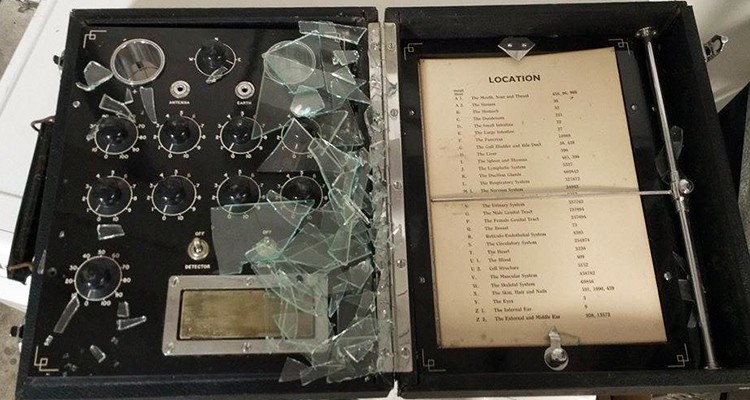
de la Warr Analyser (2)
I have recently restored the control panel of this instrument. The tuning knobs are not in the best shape, but I have polished them as best I can and made necessary repairs. We have made a model of the old style knobs used on this instrument, but most manufacturer need a MOQ of 1000 pcs which is quite excessive just for a few restoration items. I have not been able to find any new old stock anywhere so we are stuck with the old ones. These knobs look to have taken damage from the broken glass while in transit.
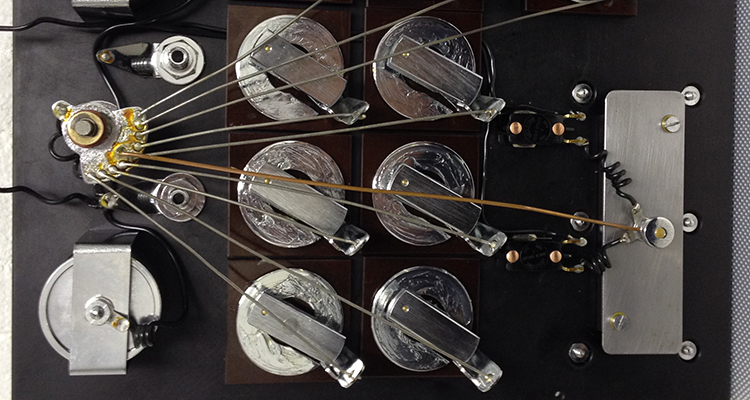
The process of restoring this panel required the complete disassembly of all the components. Well it didn’t NEED to be completely taken apart, but I’m a sucker for detail, and this way I was able to clean each and every piece of hardware. Furthermore it’s solve et coagula which allows me mastery over the instrument.