hulda clarke Posts

The Rife Crane Pad System

Rife Crane 1a

This electrode style Rife device know in Rife circles as a PAD system was developed as a commission. It is essentially a modification of a highly effective electronic circuit designed to “Zap” warts, known as the Wart Zapper, and created by Thomas Scarborough which can be found at this link: Wart Zapper

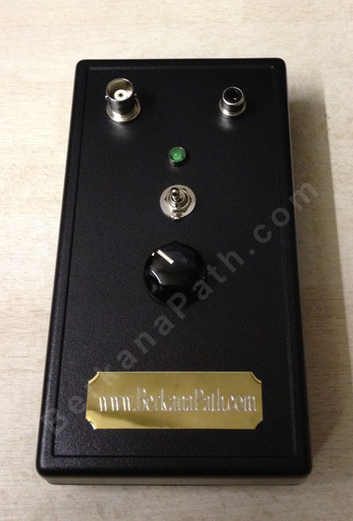
The modification allows for the injection of certain Rife frequencies at the power stage. On a decent oscilloscope the frequency harmonics can be readily observed. Wearing the electrodes the tingling sensation is clearly felt even at the lowest power setting. The power can be adjusted by turning the small Bakelite dial. The setup is full clockwise the the maximum power position which gives a peak voltage of 24-25V depending on the battery voltage levels.

I wont make any health claims here or I’ll end up with a bunch of heavies in suits coming round to my lab and stomping on my toys!

I originally wanted to work with Ken Uzzell’s Frex amp, but found the power using the signal generator was simply too low. His amp works well for the Frex software running through a sound card as you would expect, but it’s simply not good enough for a low power, low voltage signal generator. I managed to amp the power from the signal gen with a power IC, but the breakdown frequency was about 200KHz. What I really need is a full spectrum power amp, if anyone knows where I can source one I’d appreciate an email.

15Hz Zapper Schematic

I have uploaded my own personal schematic of a 15Hz zapper circuit. I spent some time trying to find a good schematic to follow last year, but I discovered that most of them were flawed and the timing formulas did not equate their components to being the correct 15Hz output. To remedy this, I drew my own schematic, built the circuit on a breadboard and tested the output using an oscilloscope. (Yes I test my circuits, unlike some armchair engineers) It is quite difficult to get an analogue circuit dead on 15Hz due to the poor tolerance of the components. The best tolerance you can get for this particular circuit components are 1% for the resistors and 2% for the capacitors. All of this considering, I managed to get the zapper circuit tuned to 15.15Hz using the variable resistor. Without the tuning, the circuit could output anywhere from 12-20Hz.

While this circuit is labelled as a zapper circuit it does not necessarily need to be used for that purpose. I originally used this circuit to pulse a scalar coil. I found that the circuit output, while o.k for zapper functionality has a very low power output for use with a coil. To remedy this issue, I have recently redesigned the circuit with a small power amplifier included, which significantly boosts the output from the coil.

Some other things for you to consider when using the zappers are the electrodes themselves. Instead of using two hand held copper electrodes, why not create a true anode and cathode by having a Zinc and a copper electrode? The results are quite interesting.

To view a larger image of the schematic, just click on the image, and it will take you to the full size drawing.

Related Blogs

  • Related Blogs on 15Hz zapper circuit