radionic Posts

Radionics Machine – Wickenden Device V.02

Radionics Machine – Wickenden Device V.02

I have decided to commercially launch Berkana Labs. This is to provide individuals with the opportunity to purchase high quality radionic and aethertronic instruments.

To kick off this commercial venture I have developed the Wickenden Device V.02. The plan was to develop an entry model which packs a punch. I have based the aesthetic design off of the classic wickenden device, but the core of the instrument has had a complete overhaul. The amplifier has been re-imagined, and re-engineered to provide even more power. I wanted to be able to include a few other functions so after a fair amount of research and development I was able to include the following functions:

  • Stochastic resonance subtle signal transfer and amplifier.
  • Automated remedy maker.
  • A vibro potentiser.
  • A proprietary system clearing function.
  • Universal mains voltage power supply.

Radionics Schematic: Super Simple Three Dial


Presented here for your delectation is a super simple three dial radionics schematic. There is no techno jargon, or standard schematic imagery. The circuit is simple as shown. The black lines represent wires, and their connections. The bottom row of wiring simply shows that the last post on each potentiometer is connected to the last post on the next.

This type of circuit is also known within radionics as a passive resistance circuit. There are no coils, crystals, or amplifiers within this circuit, but that does not detract from its raw power. Generally, this circuit can be used to copy homeopathic remedies, or for imbuing a witnesses sample with a particular trend. For the latter, the witness sample would be placed on the output, and the trend would be placed on the input. The trend could take the form of a remedy, written or pictorial intention, etc. For use in agricultural radionics for instance; fertilizer, or pesticides could be placed on the input plate, and their rates dowsed for with a pendulum.

What you will need:


  • Two copper discs, or copper sheets. Copper is not necessary, but it by far the best candidate for our purpose. If you are struggling to find copper, you can use brass, aluminium, or stainless steel as a last resort. If you are extremely lucky, you can even use gold, or silver sheet!


  • Three potentiometers. These are “10K linear potentiometers” run an internet search, or look on places like ebay for these components. Failing that try your local electronics supplier such as Maplins, or Radio Shack.


  • You will need a length of wire to wire up the potentiometer. Some researchers use solid clear enameled copper wire, but I find regular bell wire or equipment wire works just as well. Again, you can get some regular stranded single core wire from hardware stores or online. You will probably need less than a meter for this, but just to be on the safe side, and to have some surplus for a future project, get hold of a meter, or several feet worth.


  • You will also need something for stripping the wire; a pair of wire cutters can be used once you get the hang of it, or a craft knife.
  • In order to connect the wires to the potentiometers, you will need to Solder. For a beginner with no electronics experience, this is often a stumbling block. You can get hold of cheap soldering irons on the internet. You will only need something rated at 25-30W. Get yourself a book on soldering for beginners, and a reel of silver based solder. It really is quite easy to do, and once you learn this new skill you can use it for future projects.If this still puts you off, there is a product called “Wire glue” which will literally allow you to glue the wires to the potentiometers and plates. Failing that you could use some electrical tape. I wouldn’t advocate this, but it is possible as a last resort.


  • You will also need some type of box to mount everything in. Charles Cossimano suggests a shoe box. This can work well if you are on a budget. Personally, I use wooden boxes where possible. However, if you really have to, an ABS plastic box will work o.k.


  • In order to mount the potentiometers. You will require a drill, and selection of drill bits.
  • Finally; x4 bolts x8 washers, and at least four nuts. To top this off three potentiometer dials. Again, these are available from places such as Ebay, and Radio Shack, etc.


Once you have all your components you can begin to build to the above diagram. You should have chosen an enclosure/box which will allow you enough room to mount everything on one surface, usually the top. If it doesn’t, not to worry; some people will mount the plates on the top surface, and the dials on one of the sides to make more room.


It’s quite simple from here on in. Use your intuition, and build an instrument which you find visually and aesthetically appealing, as this will increase its potential. You are imbuing the device with your own power, use it wisely.


This information is free to copy and distribute. All I ask as my copyright condition is that you attribute the work back to BerkanaPath.com. These posts and diagrams take a great amount of work, and it is saddening when people abuse the work of others. This is why I am being forced to watermark all of my intellectual properties. Thank you for understanding.


Copen Restoration Project 1

I have been fortunate to acquire three original Bruce Copen Radionic Instruments. Unfortunately, they were in quite a state when I received them. The images below are of a nine dial base 10 resistance instrument. I can’t seem to find any information on this, but judging by the pass dates on the old Colvern potentiometers, it is from the early to mid 50s. Looking at the general grime build up and rust on the nickel fittings, I can only assume it had been stored in damp conditions for a number of years, most likely in a shed or barn. It is sad to think that these impressionable instruments were left neglected, their original owner no longer able to care for them. At one point, they were used extensively to manufacture homeopathic remedies. A lot of the surviving vials came with the lot. However, I have no use for vintage remedies so have stored them away. If anyone is interested in the vials, please get in touch.


I am slowly, working my way through the restoration, and am making good progress. I have decided to tackle this nine dial instrument first, as it is the easiest. Currently, I have fully cleaned up the casing, and replaced the fixings with brand new nickel latches and hinges from the original company. I have also replaced the leather strap handle on the front. The inside lid has been lined with red card, reflecting the original intentions of using paper, which was too damp and dirty to re-use. I will upload some new photos on another post over the next few weeks. Currently, I’m working on the control panel. Sadly only one of the original potentiometers is in full working order, luckily it is the one which can’t be easily replaced. Copen’s wiring is the most unusual. On this nine dial instrument, you have three logarithmic carbon track 1Megaohm pots, then one 50k linear carbon track. The remaining five in the sequence are Colvern wirewound’s which go from 100k, 10k, 1k, 100R, and 10R I can see the logic in the last five as the resistance steps down, but it’s almost as if Copen has rummaged in his parts box to make up the first four in the stage. This initial 3-4M of resistance is seen in the other instruments I have. It would make more sense if they stepped down like the others and were all linear. It’s a mystery!


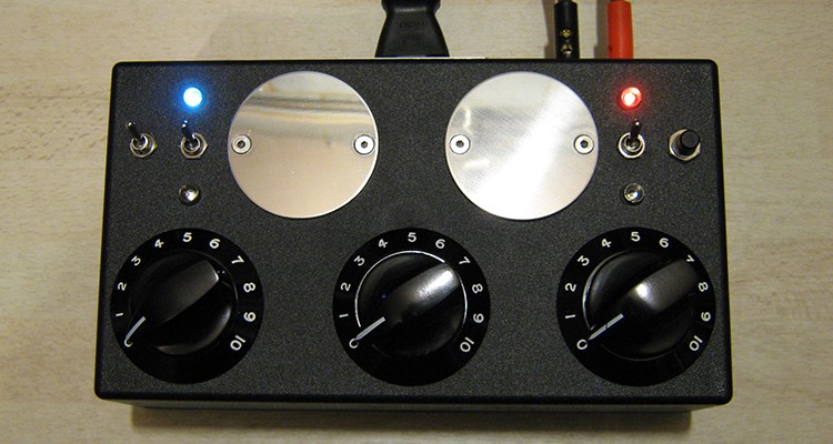
The neon lamp on this instrument is wired in an unusual manner, so that it is turned off when the power is in the off position. I suspect the original owner fiddled with the wiring at some point in its history. I intend to rewire the circuit with the same type of wire Copen used, and replace the shot pots, but leave the unusual configuration intact, aside from the neon lamp which I will change to reflect the correct way of operation as seen in the other instruments I have. I look forward to presenting the fully restored instrument to you in a new article.


Update: 18th April

Some of the potentiometers aren’t as damaged as I originally thought. A great deal of tuner cleaner, and they appear to work o.k. Its not to my usual high standards, but what can you expect from components that are sixty odd years old?! The resistances are all o.k and within the manufacturer’s tolerance range, it’s just the movement  is not as fluid or consistent as I would have liked, and this may present a problem when tuning the instrument. I have several wirewounds en route, so it should not be a problem. I would like to keep the originals where I can.

Furthermore, the card lining the lid has begun to peel away. I may just go and Araldite a sheet of thin felted, or vinyled wood to the lid to get around this problem. In any case, I will stick with the red as it compliments the red leather of the case.


The clogged up dials on the control panel are clearly visible in this image. It has since been completely taken apart and cleaned. The dials look as good as new now.