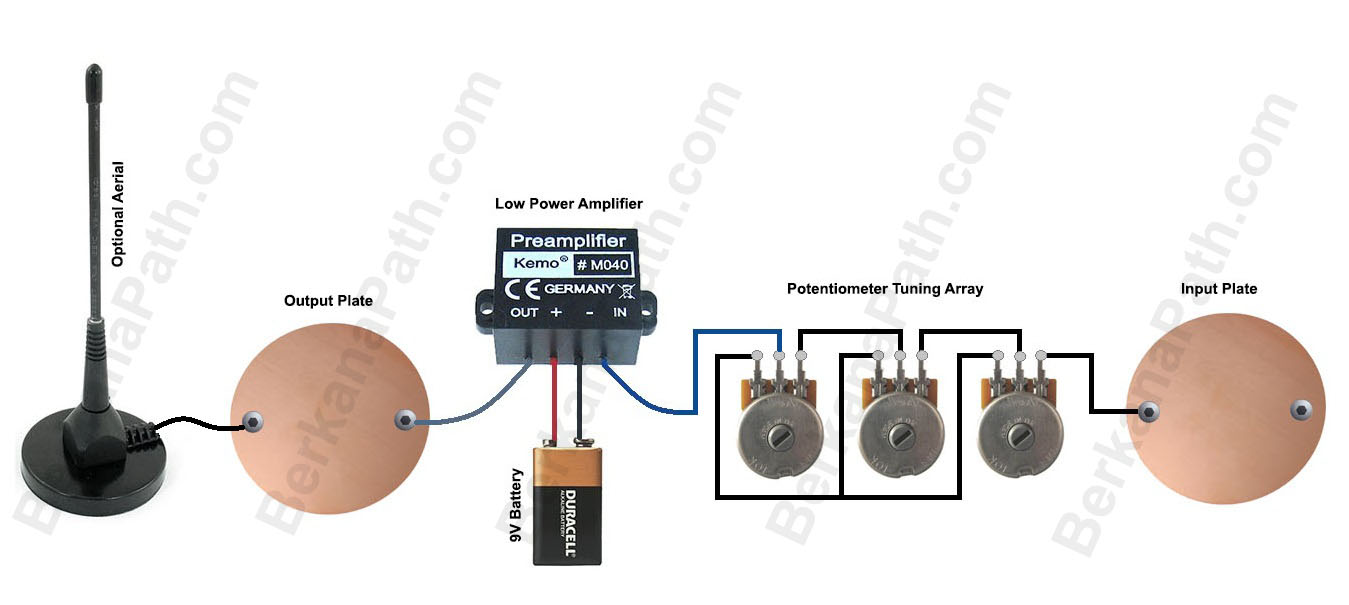
Presented here for your delectation is a super simple three dial radionics schematic. There is no techno jargon, or standard schematic imagery. The circuit is simple as shown. The black lines represent wires, and their connections. The bottom row of wiring simply shows that the last post on each potentiometer is connected to the last post on the next.
This type of circuit is also known within radionics as a passive resistance circuit. There are no coils, crystals, or amplifiers within this circuit, but that does not detract from its raw power. Generally, this circuit can be used to copy homeopathic remedies, or for imbuing a witnesses sample with a particular trend. For the latter, the witness sample would be placed on the output, and the trend would be placed on the input. The trend could take the form of a remedy, written or pictorial intention, etc. For use in agricultural radionics for instance; fertilizer, or pesticides could be placed on the input plate, and their rates dowsed for with a pendulum.
What you will need:
- Two copper discs, or copper sheets. Copper is not necessary, but it by far the best candidate for our purpose. If you are struggling to find copper, you can use brass, aluminium, or stainless steel as a last resort. If you are extremely lucky, you can even use gold, or silver sheet!
- Three potentiometers. These are “10K linear potentiometers” run an internet search, or look on places like ebay for these components. Failing that try your local electronics supplier such as Maplins, or Radio Shack.
- You will need a length of wire to wire up the potentiometer. Some researchers use solid clear enameled copper wire, but I find regular bell wire or equipment wire works just as well. Again, you can get some regular stranded single core wire from hardware stores or online. You will probably need less than a meter for this, but just to be on the safe side, and to have some surplus for a future project, get hold of a meter, or several feet worth.
- You will also need something for stripping the wire; a pair of wire cutters can be used once you get the hang of it, or a craft knife.
- In order to connect the wires to the potentiometers, you will need to Solder. For a beginner with no electronics experience, this is often a stumbling block. You can get hold of cheap soldering irons on the internet. You will only need something rated at 25-30W. Get yourself a book on soldering for beginners, and a reel of silver based solder. It really is quite easy to do, and once you learn this new skill you can use it for future projects.If this still puts you off, there is a product called “Wire glue” which will literally allow you to glue the wires to the potentiometers and plates. Failing that you could use some electrical tape. I wouldn’t advocate this, but it is possible as a last resort.
- You will also need some type of box to mount everything in. Charles Cossimano suggests a shoe box. This can work well if you are on a budget. Personally, I use wooden boxes where possible. However, if you really have to, an ABS plastic box will work o.k.
- In order to mount the potentiometers. You will require a drill, and selection of drill bits.
- Finally; x4 bolts x8 washers, and at least four nuts. To top this off three potentiometer dials. Again, these are available from places such as Ebay, and Radio Shack, etc.
Once you have all your components you can begin to build to the above diagram. You should have chosen an enclosure/box which will allow you enough room to mount everything on one surface, usually the top. If it doesn’t, not to worry; some people will mount the plates on the top surface, and the dials on one of the sides to make more room.
It’s quite simple from here on in. Use your intuition, and build an instrument which you find visually and aesthetically appealing, as this will increase its potential. You are imbuing the device with your own power, use it wisely.
This information is free to copy and distribute. All I ask as my copyright condition is that you attribute the work back to BerkanaPath.com. These posts and diagrams take a great amount of work, and it is saddening when people abuse the work of others. This is why I am being forced to watermark all of my intellectual properties. Thank you for understanding.